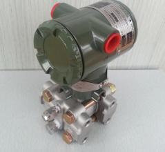


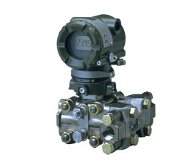
- 产品名称:EJA115微小流量变送器
- 浏览:
 咨询热线:13920037278 022-24300522
 点击留言
点击留言
| 详细介绍 | |||||||||||||||||||||||||||||||||||||||||||||||||||||||||||||||||||||||||||||||||||||||||||||||||||||||||||||||||||||||||||||||||||||||||||||||||||||||||||||||||||||||||||||||||||||||||||||||||||||||||||||||||||||||||||||||||||||||||||||||||||||||||||||||||||||||||
|
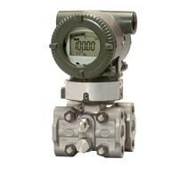
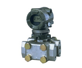
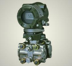
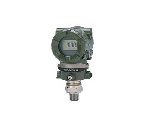
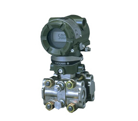
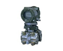
EJA115微小流量变送器 EJA115微小流量变送器EJA115微小流量变送器内藏孔板,适用于微小流量测量。 产品信息
特性
规格
产品选型
The ‘#’marks indicate the construction materials conform to NACE material recommendations per MR01-75. For the use of SUS316 material, there may be certain limitations for pressure and temperature. Please refer to NACE standards for details. *1: Refer to GS 01C22T01-00E for HART Protocol version.*2: Diaphragm material is Hastelloy C-276 or ASTM N10276. Other capsule wetted parts materials are JIS SUSF316L, SUS316L or ASTM grade 316L. *3: Indicates material of cover flange and process connector. Material of manifold is JIS SUSF316. Material of vent plug is JIS SUS316 or ASTM grade 316. *4: If necessary, specify Mounting bracket code C, D or K. *5: If necessary, specify Mounting bracket code A, B or J. *6: Refer to GS 01C22T02-00E for Fieldbus communication. *7: Not applicable for Output signal code F and G. *8: Users must consider the characteristics of selected wetted parts material and the influence of process fluids. The use of inappropriate materials can result in the leakage of corrosive process fluids and cause injury to personnel and/or damage to plant facilities. It is also possible that the diaphragm itself can be damaged and that material from the broken diaphragm and the fill fluid can contaminate the user's process fluids. Be very careful with highly corrosive process fluids such as hydrochloric acid, sulfuric acid, hydrogen sulfide, sodium hypochlorite, and high-temperature steam (150°C [302°F] or above). Contact Yokogawa for detailed information of the wetted parts material. *9: Refer to GS 01C22T03-00E for PROFIBUS PA communication. |
|||||||||||||||||||||||||||||||||||||||||||||||||||||||||||||||||||||||||||||||||||||||||||||||||||||||||||||||||||||||||||||||||||||||||||||||||||||||||||||||||||||||||||||||||||||||||||||||||||||||||||||||||||||||||||||||||||||||||||||||||||||||||||||||||||||||||